Excavator Hydraulic Diagnostics: A Technical Guide to Field Troubleshooting (2026)
Replacing a primary hydraulic pump when the actual failure lies in a simple relief valve isn’t just a maintenance error. It’s a costly failure of technical discipline that compromises project timelines and operational budgets. Most fleet managers recognize the frustration of unplanned job site downtime and the compounding expenses of the “parts cannon” approach to repairs. Guesswork in the field often leads to secondary failures and avoidable capital expenditure.
This technical guide establishes a professional methodology for excavator hydraulic diagnostics to isolate root causes and prevent unnecessary component damage. You’ll master the rigorous protocols required to make definitive repair versus replace decisions and restore machine efficiency. We will analyze modern diagnostic workflows, incorporating updated standards like ISO 8643:2024 for lowering control devices and the application of 2026 software versions such as Cummins Insite 9.3 Pro. By adopting these engineering-grade troubleshooting standards, technicians can transition from reactive guessing to precise data-driven system verification.
Key Takeaways
- Implement a structured five-step isolation protocol to move beyond speculative repairs and identify specific component failures within complex hydraulic circuits.
- Utilize high-pressure gauge kits and digital flow meters to verify system integrity and pump efficiency against precise manufacturer specifications.
- Master the specialized techniques for excavator hydraulic diagnostics to distinguish between internal seal failures and control valve spool wear.
- Reduce operational downtime by leveraging professional on-site troubleshooting and mobile fabrication services to address failures directly at the job site.
- Maintain system cleanliness and document machine symptoms under load to ensure accurate root cause identification and prevent secondary component damage.
The Engineering Foundation of Excavator Hydraulic Diagnostics
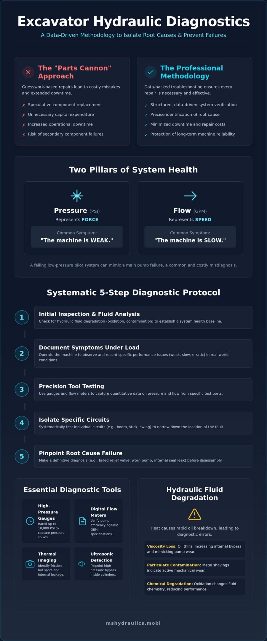
Professional excavator hydraulic diagnostics is a disciplined engineering process. It involves the systematic isolation of pressure, flow, and mechanical integrity within a complex circuit. This methodology relies on The Engineering Foundation of Excavator Hydraulic Diagnostics to identify specific failure points before any physical teardown occurs. Many fleet managers fall into the trap of the “parts cannon” approach. They replace expensive pumps or control valves based on a superficial hunch. This strategy is rarely successful. It creates massive unplanned costs and extends machine downtime. Data-backed troubleshooting ensures that every repair is necessary and effective. Whether a machine uses an older open-center architecture or a modern closed-loop, load-sensing system, the diagnostic logic remains the same. Technicians must verify the performance of individual components against original equipment manufacturer (OEM) specifications.
Engaging On-Site Diagnostic Services is the most efficient way to capture performance data under actual operating loads. Opening a hydraulic system in a dirty field environment without a clear diagnostic path is a risk. It introduces particulates that can destroy precision-machined valve spools. A structured diagnostic plan protects the machine’s long-term reliability by minimizing system exposure and focusing on the root cause.
Pressure vs. Flow: The Two Pillars of System Health
System health is defined by the relationship between pressure and flow. Pressure, measured in PSI, represents the force the machine can exert. Flow, measured in GPM, determines the speed of the actuators. If an excavator is “weak” and cannot break through material, the issue usually involves pressure relief settings or pump compensators. If the machine is “slow” but maintains breakout force, the problem is likely a loss of flow. Technicians must also evaluate the pilot system. This low-pressure circuit controls the main pump output. A failing pilot pump can mimic a total main pump failure. This leads to unnecessary and expensive pump replacements when a simple pilot adjustment or seal could have solved the issue.
The Impact of Hydraulic Fluid Degradation
The intense North Texas heat causes rapid chemical breakdown of hydraulic oil. Viscosity loss is a primary driver of diagnostic errors. When oil thins out, internal bypass increases. This often results in false readings of pump wear. During an initial inspection, technicians look for two types of problems: chemical degradation and particulate contamination. Oxidation changes the fluid’s chemistry, while metal shavings indicate mechanical wear. Fluid analysis is the critical first step in professional Heavy Equipment Maintenance. It provides an objective baseline for the internal health of the entire system.
Essential Diagnostic Tools and Technical Parameters
Precision in excavator hydraulic diagnostics requires more than a basic toolkit. It demands high-performance instrumentation capable of capturing transient pressure spikes and subtle flow fluctuations. Technicians must utilize high-pressure gauge kits rated up to 10,000 PSI. This range is necessary to monitor system surges that exceed standard operating pressures, which often indicate failing relief valves or blocked orifices. Digital flow meters provide the second layer of critical data. These tools verify pump efficiency under load by measuring the actual output against the theoretical displacement. Without these metrics, a technician is merely guessing at the internal health of the machine.
Modern field troubleshooting also leverages thermal imaging and ultrasonic detection. Thermal cameras identify friction hot spots and internal valve leakage by visualizing temperature differentials across the hydraulic manifold. Similarly, ultrasonic leak detectors pinpoint high-pressure bypass inside cylinders that might not be visible externally. These methods align with Systematic Fault Isolation principles, ensuring that every diagnostic step is verifiable and repeatable. If your team lacks these advanced tools, utilizing professional on-site diagnostic support can prevent the misdiagnosis of expensive core components.
Calibrating the Pilot and Main Systems
Accurate calibration begins with the pilot system. Most standard excavator pilot systems operate within a target range of 450 to 600 PSI. If this pressure is too low, the main control valve spools won’t shift fully, leading to sluggish performance. Main relief valves must also be set precisely to protect the pumps from catastrophic failure during heavy breakout operations. Technicians should consult specific Hydraulic Parts documentation to ensure every adjustment meets the manufacturer’s performance curve. These small adjustments often resolve “weak” machine symptoms without the need for a full pump rebuild.
Electronic Diagnostic Integration
Modern excavators rely heavily on the Machine Control Unit (MCU) to manage hydraulic output. Reading error codes is a mandatory step in excavator hydraulic diagnostics to identify solenoid failures or proportional valve lag. While electronic sensors provide real-time data on the operator’s display, they aren’t infallible. Mechanical gauges remain a necessary redundancy to verify that the digital readings match the physical reality of the system. This dual-verification process ensures that an electrical fault isn’t mistaken for a mechanical breakdown, saving hours of unnecessary labor and component costs.
A Systematic 5-Step Process for Field Diagnostics
Field diagnostics in an uncontrolled environment present significant risks. Contamination remains the primary cause of hydraulic component failure. Before opening any lines on a job site, technicians must ensure the work area is as clean as possible. A systematic approach to excavator hydraulic diagnostics prevents the introduction of debris into precision-toleranced components. This disciplined workflow replaces the inefficient “trial and error” method with a logical sequence of verification steps.
The first technical requirement is to verify the engine’s performance. It’s a common error to troubleshoot the hydraulic system when the engine is failing to reach its rated RPM or power output. If the engine lacks the torque to drive the pumps at full displacement, the hydraulics will appear weak or unresponsive. Once the engine is verified, the technician must document symptoms at specific operating temperatures. Hydraulic oil viscosity changes significantly as it warms. This can mask or highlight internal bypass issues that aren’t apparent when the machine is cold.
Isolation is the next critical phase. By testing the Swing, Boom, Bucket, and Travel circuits independently, a technician can determine if the fault is localized to one function or systemic across the entire machine. If only the boom circuit is slow, the issue likely resides in that specific control valve or cylinder rather than the main pump.
Step 1 & 2: Visual Inspection and Thermal Mapping
The process begins with a comprehensive visual scan. Technicians look for external leaks, hose abrasions, and cylinder rod scoring. Any damage to a rod can pull contaminants directly into the cylinder seals. Infrared thermography is then used to locate internal bypass. A “hot” valve in a neutral position indicates high-pressure fluid is slipping past a seal or spool, generating heat through friction. Finally, the reservoir is inspected for aeration. Foaming fluid usually indicates a suction line leak. This leads to pump cavitation and eventual failure if left unaddressed.
Step 3, 4, & 5: Pressure, Flow, and Cycle Time Testing
Once visual and thermal data are collected, the technician performs “stall” tests. This involves bottoming out a cylinder to force the system into a relief state. This verifies if the relief valves are opening at the correct OEM-specified PSI. Following this, cycle times for all major functions are measured and compared against the machine’s factory specifications. A slow cycle time at correct pressure confirms a flow loss, often pointing to pump wear. The final step is a rigorous load test. This ensures the repair is stable under the machine’s maximum rated capacity before it’s released back to the job site.
Troubleshooting Primary Excavator Hydraulic Failure Modes
Environmental factors in North Texas significantly accelerate hydraulic degradation. The combination of triple digit summer temperatures and abrasive dust in the Cleburne area creates a high stress environment for seals and pumps. Professional excavator hydraulic diagnostics must account for these variables. High ambient heat lowers the viscosity of hydraulic fluid, which increases internal bypass and makes subtle mechanical wear much more apparent. When oil thins, the cooling system’s efficiency becomes the machine’s primary defense against component fatigue, much like how E.R.S. Heating & Cooling ensures that commercial cooling systems remain reliable under extreme environmental loads.
Pump cavitation is a critical failure mode characterized by a distinct “marbles in a can” sound. This occurs when the pump cannot draw enough fluid, creating vacuum bubbles that implode with enough force to pit metal surfaces. Common causes include clogged reservoir breathers or restricted suction strainers. If left unaddressed, cavitation leads to total pump destruction within hours of operation. Technicians also monitor for cylinder drift, which is a choice between a failing piston seal or a worn control valve spool. A bypass test is necessary to confirm which component requires service before committing to a teardown.
Pump and Motor Failure Analysis
Wear in gear, vane, or piston pumps typically manifests as a gradual loss of speed and power as the system warms. Case drain flow testing is the objective standard for determining the health of hydraulic motors and pumps. If the case drain flow exceeds OEM limits, internal clearances have opened up beyond the point of efficient operation. In many instances, persistent drift or leakage indicates that a Heavy Equipment Cylinder Rebuild is the only viable path to restoring factory spec performance. For immediate assistance with failing components, you can schedule professional mobile hydraulic repair to minimize site downtime.
Valve and Hose Integrity
The Main Control Valve (MCV) manages the distribution of oil to all functions. Internal leaks here cause erratic movement or “ghost” functions where one circuit moves when another is activated. Hose failures aren’t always external. Internal liners can collapse, creating an invisible blockage that mimics a failing valve or pump. This is why on-site hose fabrication is critical during a diagnostic call. It allows for the immediate replacement of suspect lines to verify circuit integrity without waiting for parts delivery. Maintaining relief valve “cracking” pressure is also vital. If a valve opens too early, the system generates excessive heat, leading to rapid oil oxidation and accelerated seal failure.
Professional Mobile Diagnostics in North Texas
The decision to transport a disabled excavator to a central repair facility is often a logistical and financial burden. Hauling fees for heavy equipment involve significant overhead, including specialized permits and dedicated transport teams. By utilizing Mobile Hydraulic Repair Cleburne TX, fleet owners bypass these secondary costs. Expert on-site excavator hydraulic diagnostics provide immediate clarity on whether a machine requires a simple valve adjustment or a complex pump replacement. This rapid response is critical in the Cleburne, Dallas, and Fort Worth corridor, where project timelines are rigid and downtime penalties are severe. Bringing the diagnostic laboratory directly to the machine ensures that the system is tested under the exact environmental conditions where the failure occurred.
Ms. Hydraulics LLC reduces total ownership costs by replacing guesswork with data-driven troubleshooting. Our mobile units are equipped with the high-pressure instrumentation and flow meters described in previous sections. This allows for the precise isolation of failures without the need for machine relocation. This approach doesn’t just save on haulage; it prevents the potential for further mechanical damage that can occur when moving a machine with a compromised hydraulic circuit. Establishing a professional diagnostic partnership is the most effective way to build long-term fleet reliability and ensure that capital is only spent on verified repairs.
Why Local Expertise Matters for Texas Fleet Owners
North Texas soil conditions, particularly the high clay content and abrasive dust found in the DFW area, demand specialized maintenance knowledge. These elements accelerate seal wear and increase the risk of particulate contamination during field service. We understand the specific wear patterns caused by the intense heat in Alvarado, Granbury, and Mansfield. Our mobile service includes the rapid availability of custom hoses, allowing us to restore circuit integrity immediately after a failure is identified. We maintain an integrity-based service model: we fix what’s broken based on objective data, and nothing more. This disciplined approach protects your operational budget from unnecessary component replacements.
Scheduling Your Diagnostic Call
To expedite excavator hydraulic diagnostics, owners should have the machine’s make, model, and serial number ready when calling. Providing a detailed description of symptoms, such as specific “slow” functions or unusual noises, allows the technician to narrow the diagnostic scope before arrival. Preparing the machine involves ensuring it’s parked on level ground and is reasonably clean to prevent further contamination during the inspection. Once the diagnostic report is delivered, you’ll receive a clear technical summary of the system’s health. This report serves as the foundation for an informed repair vs. replace decision, ensuring the machine returns to service at its peak engineering specification.
Optimizing Fleet Performance Through Technical Precision
Transitioning from reactive component replacement to a structured diagnostic framework is the most effective way to manage heavy equipment assets. By utilizing high-pressure instrumentation and thermal mapping, technicians can isolate specific failure modes like pump cavitation or cylinder bypass without unnecessary system teardowns. This disciplined approach to excavator hydraulic diagnostics ensures that every repair is backed by objective performance data rather than speculation. Implementing these rigorous standards protects the integrity of the machine’s complex circuits and extends the service life of high-value pumps and motors; similarly, you can discover GAP Mechanical for professional HVAC services that apply this same level of technical precision to climate control systems.
Ms. Hydraulics LLC provides the technical expertise required to execute these protocols directly on your job site. Our expert technicians deliver rapid on-site diagnosis and mobile hose fabrication to minimize operational delays across Cleburne and the entire DFW Metroplex. Schedule Expert Mobile Diagnostics in North Texas to restore your machine’s engineering specifications and prevent costly secondary damage. Maintaining a high standard of hydraulic health is the surest path to project success and long-term machine reliability. Your fleet’s efficiency depends on precision, and we’re ready to provide it.
Frequently Asked Questions
What are the first signs of hydraulic pump failure in an excavator?
The most common indicators include an audible increase in noise levels, often described as a metallic whining or grinding, and a noticeable loss of actuator speed as the hydraulic fluid reaches operating temperature. Excessive case drain flow is the definitive technical sign that internal clearances have opened up. Technicians also look for “hunting” or surging in the hydraulic circuits during high-load breakout operations.
How much does a professional hydraulic diagnostic service cost in Cleburne?
Diagnostic fees vary based on the complexity of the machine’s control system and the specific travel requirements within the North Texas region. Since every failure scenario is unique, fleet owners should contact a service provider directly for a quote tailored to their specific make and model. Investing in an expert assessment is generally more cost-effective than the speculative replacement of high-value components.
Can I diagnose a hydraulic leak without specialized tools?
Visual inspections can identify external hose ruptures or weeping cylinder seals, but they cannot detect internal bypass. Determining if a cylinder is drifting due to a piston seal failure or a worn control valve spool requires instrumentation like flow meters or thermal imaging. Attempting excavator hydraulic diagnostics without the proper gauges usually results in inaccurate conclusions and unnecessary downtime.
Why is my excavator moving slowly even though the engine sounds fine?
Sluggish movement with a healthy engine typically points to a loss of hydraulic flow rather than a lack of pressure. This often stems from internal pump wear, a restricted suction strainer, or a pilot system that fails to provide the 450 to 600 PSI required to fully shift the main control valve spools. If the flow (GPM) is insufficient, the actuators will move slowly regardless of the engine’s RPM.
How often should I perform hydraulic pressure testing on my fleet?
Pressure testing should be integrated into a 1,000-hour preventive maintenance schedule or performed whenever cycle times deviate from OEM specifications. Regular excavator hydraulic diagnostics allow for the early detection of relief valve drift or pump compensator wear. Catching these issues early prevents the secondary heat damage that leads to total system failure.
What causes hydraulic fluid to overheat on a North Texas job site?
Thermal issues are usually caused by a combination of high ambient temperatures and reduced cooling efficiency due to dust accumulation in the heat exchanger. Mechanical causes include relief valves that “crack” below their rated pressure, which forces oil through a narrow orifice and generates massive friction heat. Maintaining the correct oil viscosity is critical in the DFW climate to ensure the cooling circuit operates within its designed parameters.
Is it better to repair or replace a failing hydraulic pump?
The decision depends on the extent of the “hard” part damage identified during the teardown. If the pump housing is severely scored or the shaft is damaged, replacement is usually the only reliable option. However, if the wear is limited to the rotating group or seals, a professional rebuild can restore the unit to factory performance levels at a lower cost than a new assembly.
How long does a typical on-site hydraulic diagnostic call take?
A comprehensive field assessment generally requires two to four hours of technician labor. This timeframe includes the initial visual inspection, the installation of diagnostic gauges, and the execution of stall tests to capture system data under load. Providing the technician with the machine’s serial number and a detailed history of symptoms before they arrive can often expedite the isolation process.