Troubleshooting Hydraulic Motor Problems: A Technical Diagnostic Guide
Treating a hydraulic motor as an isolated component is the most common diagnostic error in heavy equipment maintenance. You’ve likely experienced the frustration of a machine losing torque or overheating on a North Texas job site, only to find that replacing the motor didn’t solve the underlying issue. The “shotgun” approach of replacing parts without a definitive diagnosis is a costly gamble that leads to repeated unplanned downtime and lost productivity.
This guide establishes a systematic framework for troubleshooting hydraulic motor problems by analyzing the motor as part of a complete circuit. You’ll master the technical steps required to move beyond guesswork to precise engineering diagnostics. We will examine how to perform on-site pressure and flow testing, identify internal bypass issues, and evaluate physical parameters to determine if a motor can be rebuilt or must be replaced. By following these rigorous diagnostic standards, you can pinpoint the exact cause of failure and implement solutions that prevent recurrence. This methodical approach ensures your machinery returns to service with verified reliability.
Key Takeaways
- Identify the technical significance of abnormal acoustic signatures and excessive heat to differentiate between fluid contamination and mechanical wear.
- Execute a systematic approach to troubleshooting hydraulic motor problems by isolating pressure and flow variables to pinpoint specific power losses.
- Quantify internal bypass and assess volumetric efficiency through precise case drain flow measurement before committing to a full motor teardown.
- Establish performance baselines using standardized cycle time tests and visual contamination checks to expedite on-site diagnostics for mobile heavy equipment.
- Leverage professional diagnostic data to determine the viability of a motor rebuild, ensuring a return to OEM specifications while minimizing total repair costs.
Recognizing Primary Symptoms of Hydraulic Motor Failure
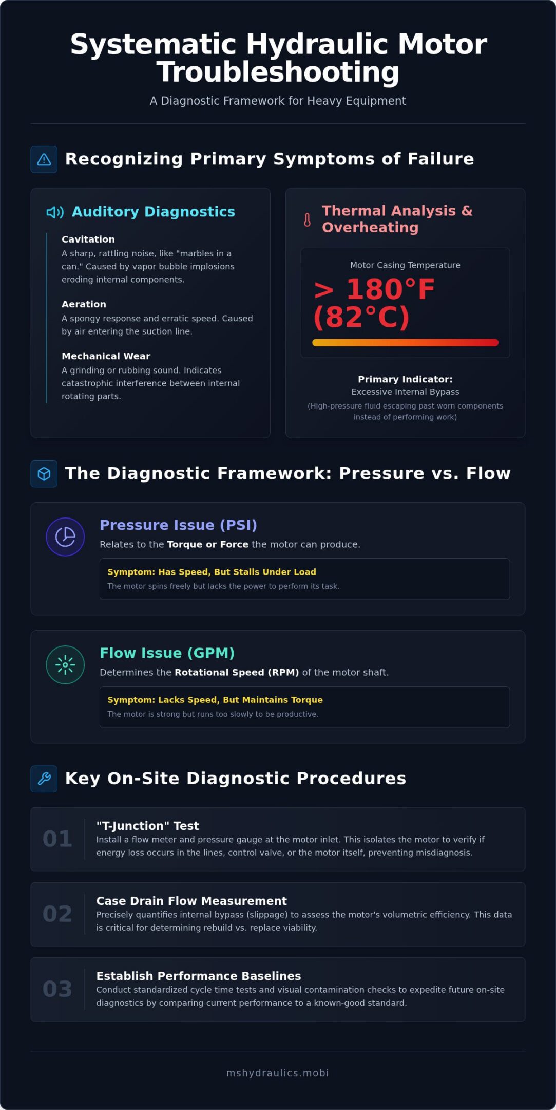
Effective troubleshooting hydraulic motor problems begins with a rigorous sensory assessment. Technical failure rarely occurs in isolation; it manifests through measurable changes in acoustic output and thermal profiles. Operators must distinguish between normal operational hums and the distinct signals of mechanical or hydraulic distress. A high-pitched whining often indicates fluid-related stress, while grinding or a “marbles in a can” sound signals catastrophic mechanical interference between internal rotating groups.
Auditory Diagnostics: Cavitation vs. Aeration
Cavitation occurs when a vacuum forms within the motor, causing vapor bubbles to implode against metal surfaces with extreme force. This process erodes internal components and creates a sharp, rattling noise. Aeration involves air entering the suction line, leading to a spongy response and erratic output speed. Technicians should use an industrial stethoscope to pinpoint whether friction originates from the bearing set or the valve plate. Identifying these sounds early prevents the total destruction of the rotating group in heavy equipment like excavators or drill rigs.
Thermal Analysis and Overheating
Measuring the temperature differential between inlet and outlet ports is a standard diagnostic procedure. In the high-ambient temperatures of North Texas, thermal breakdown of hydraulic fluid occurs rapidly if the motor casing temperature exceeds 180°F. A significant temperature spike at the motor casing usually indicates excessive internal bypass. This happens when high-pressure fluid escapes past worn internal tolerances rather than performing mechanical work. As heat increases, fluid viscosity drops, which leads to increased slippage and a further rise in operating temperatures.
Monitoring the rate of performance decline is equally critical. A gradual loss of output speed or torque suggests a steady degradation of volumetric efficiency, often caused by normal wear on the piston bores or gear teeth. Conversely, a sudden loss of function typically indicates a snapped drive shaft or a seized internal component. Technicians must also perform a visual inspection for external indicators. Shaft seal leaks are often a secondary symptom of excessive case pressure, while hairline housing cracks suggest the motor has been subjected to pressure spikes that exceeded its peak design rating. Identifying these symptoms during the initial phase of troubleshooting hydraulic motor problems ensures that the diagnostic process remains focused on the root cause rather than just the visible damage.
The Diagnostic Framework: Pressure vs. Flow Issues
Systematic troubleshooting hydraulic motor problems requires a clear distinction between pressure and flow. Pressure is the measure of resistance to flow and directly correlates to the torque or force the motor produces. Flow, measured in gallons per minute (GPM), determines the rotational speed of the shaft. If a machine lacks speed but maintains torque, the issue is likely flow-related. If it has speed but stalls under load, the issue is pressure-related. Distinguishing between these two physical parameters is the only way to avoid the high cost of “shotgunning” parts without a technical diagnosis.
Determining the root cause requires isolating the motor from the rest of the circuit. A common error is assuming a motor is faulty when the main relief valve is bypassing or the pump’s volumetric efficiency has dropped. The “T-junction” test involves installing a flow meter and pressure gauge at the motor inlet. By comparing these readings to the pump outlet, technicians can verify if the energy loss occurs in the lines, the control valve, or within the motor itself. This methodical isolation prevents the misdiagnosis of a functional motor as a failed component.
Testing System Pressure (PSI)
Accurate diagnostics depend on proper gauge placement. Gauges must be installed at the motor inlet ports to account for pressure drops across long hose runs or restrictive valves. You should compare these actual PSI readings against the machine’s OEM specifications. If the pressure at the motor is significantly lower than the pump setting, the problem typically lies in a leaking relief valve or an internal valve stack failure rather than the motor. Professional on-site diagnostic services can verify these parameters under real-world load conditions to prevent unnecessary component replacement.
Measuring Volumetric Efficiency
Volumetric efficiency is the ratio of actual to theoretical flow. As internal components wear, slippage increases, allowing fluid to pass through the motor without contributing to shaft rotation. To calculate this, measure the flow at the motor inlet while the motor is under a known load and compare it to the manufacturer’s theoretical flow rate for that specific RPM. A motor operating at less than 80% efficiency usually indicates significant internal wear and requires immediate attention to prevent total system contamination. High case drain flow often accompanies this drop in efficiency, signaling that the internal tolerances have exceeded their service limits. Understanding these flow dynamics is essential for effective troubleshooting hydraulic motor problems in heavy industrial applications, similar to the precision engineering required for the production lines supported by Choice Bagging Equipment.
The case drain is a critical diagnostic interface that serves as the motor’s internal lubrication and cooling circuit. It directs the small amount of fluid that naturally leaks past the internal rotating group back to the reservoir. While this “blow-by” is normal for lubrication, an increase in volume indicates advanced wear on the piston bores or vane tips. Monitoring this flow is a fundamental step in troubleshooting hydraulic motor problems, as it quantifies internal bypass without requiring a full teardown. If the case drain flow exceeds the manufacturer’s specified limits, the motor is losing its ability to maintain torque and speed under load.
The Case Drain Flow Test
Measuring case drain flow provides a direct metric for the motor’s volumetric efficiency. To execute this test, disconnect the drain line and direct the output into a graduated container. Operate the motor at its normal working pressure and temperature, then record the volume of fluid collected over a 60-second interval. You should compare this value to the manufacturer’s maximum allowable leakage rate. Excessive flow indicates that the internal tolerances have widened, often due to abrasive wear or overheating. If the flow is zero or significantly restricted, check for a blockage in the return-to-tank line immediately. A blocked drain line causes case pressure to spike, which invariably leads to catastrophic mechanical failure.
Shaft Seal Integrity and Replacement
Shaft seal leaks are frequently misidentified as simple maintenance items when they’re often indicators of deeper system issues. While seal lips can fail due to the high-particulate dust common on North Texas construction sites, they more commonly fail due to excessive housing pressure. If the case drain line is restricted or if internal bypass exceeds the drain line’s capacity, the resulting pressure spike will blow the shaft seal outward. Technicians must distinguish between a seal that has reached its service life and one that has failed due to bearing play. If the shaft has perceptible radial movement, the bearings are likely failing, and replacing the seal will only provide a temporary fix. Maintaining a clean environment and ensuring the return line remains unobstructed are the most effective ways to preserve seal integrity and prevent repeat failures in heavy equipment. This level of technical scrutiny is essential for effective troubleshooting hydraulic motor problems in industrial settings.
Field Troubleshooting Procedures for Mobile Heavy Equipment
Field diagnostics require a transition from theoretical analysis to physical verification. On a job site, technicians must act quickly to prevent extended downtime. The process begins with a comprehensive visual inspection of the entire circuit. You should check for collapsed suction hoses, kinked return lines, and signs of external leakage. These physical obstructions often mimic internal motor failure by restricting flow or inducing cavitation. Identifying these external issues first prevents the unnecessary removal of functional components.
Establishing a performance baseline through a cycle time test is the next technical step. By timing a specific machine function, such as the rotation of a drill rig or the travel speed of an excavator, you can compare actual performance against original equipment manufacturer (OEM) specifications. If the cycle time is significantly slower than the factory standard, it confirms a loss of volumetric efficiency that requires deeper investigation. This quantitative data is essential for effective troubleshooting hydraulic motor problems in high-pressure mobile applications.
Contamination Control and Fluid Analysis
Rigorous heavy equipment maintenance protocols always prioritize fluid cleanliness. When troubleshooting hydraulic motor problems in the field, drawing a fluid sample from the motor case or the return filter is mandatory. Technicians must analyze the sample for metallic debris. Brass or bronze shavings typically indicate wear on piston shoes or the valve plate, while steel particles suggest failing bearings or gear teeth. Identifying these materials helps determine if the motor is a candidate for a rebuild or if the entire system has been contaminated by a catastrophic failure. Particulate matter as small as 5 microns can bridge the tolerances in modern high-speed motors, leading to rapid degradation of internal surfaces.
Isolating the Component
To confirm the motor is the root cause, you must isolate it from the directional control valve and the pump. This is achieved by using block-off plates or high-pressure plugs at the motor ports. By safely stalling the motor and monitoring the pressure at the inlet, you can verify if the system maintains the required PSI. You must also ensure that all hydraulic hose fittings are free from internal restrictions that could cause localized heat or pressure drops. If the system maintains pressure when the motor is isolated but fails when the motor is engaged, the internal bypass is confirmed. For complex failures that require precision testing, our mobile hydraulic repair teams provide the specialized equipment necessary to conduct these technical tests on-site.
Professional Hydraulic Motor Repair and Diagnostics in Cleburne
Executing professional troubleshooting hydraulic motor problems in the field requires more than just standard mechanical tools. It demands a sophisticated understanding of hydraulic theory and the specific operational demands of heavy equipment in the North Texas climate. Ms. Hydraulics LLC focuses on identifying the precise failure points that lead to system inefficiency. By prioritizing engineering precision, we ensure that every diagnostic step provides actionable data rather than speculative parts replacement. This disciplined approach is essential for maintaining the reliability of critical assets like excavators and drill rigs.
Why Mobile Diagnostics Save Money
The primary advantage of on-site diagnostic services is the immediate elimination of the “parts-changing” trap. When a motor fails on a DFW job site, the instinct is often to order a new unit immediately. However, our technicians use specialized flow meters and pressure transducers to verify if the motor is truly the source of the power loss. This technical scrutiny frequently reveals that the issue lies in a control valve or a pump setting, saving the fleet owner thousands in unnecessary hardware costs. Our mobile hydraulic repair Cleburne TX team eliminates the logistical burden and high cost of transporting massive machinery to a centralized shop for evaluation.
Precision Rebuilds and Testing
A professional rebuild is often the most technically sound and cost-effective path forward for modern industrial motors. Our process involves a meticulous disassembly where every internal component is cleaned and inspected for micro-fractures or abrasive wear. We don’t just replace standard seals; we analyze the wear patterns on the piston bores and valve plates to restore original volumetric efficiency. By utilizing high-quality seals and verified replacement parts, we ensure that the rebuilt motor meets or exceeds its original performance parameters. This level of technical integrity prevents the repeat failures that often plague less rigorous repair processes.
Our commitment to physical and mechanical accuracy ensures that your equipment returns to service with verified performance data. Troubleshooting hydraulic motor problems shouldn’t be an exercise in guesswork. It should be a structured process that values reliability and performance above all else. Owners of North Texas fleets can request a technical consultation to establish a proactive maintenance schedule that addresses potential failures before they result in catastrophic downtime. We focus on modern efficiency while respecting the legacy of industrial excellence that our partners expect.
Maximizing Operational Reliability Through Technical Precision
Mastering the nuances of volumetric efficiency and case drain diagnostics transforms reactive repairs into a disciplined maintenance strategy. By isolating the motor from the circuit and verifying physical parameters, you eliminate the high costs associated with speculative component replacement. Effective troubleshooting hydraulic motor problems ensures that your heavy equipment operates at peak design specifications while minimizing unplanned downtime. This systematic approach preserves the mechanical integrity of your entire hydraulic system.
Since 2021, Ms. Hydraulics LLC has provided specialized mobile repair and on-site diagnostics for the construction and industrial sectors throughout Cleburne and the DFW area. Our expertise in complex cylinder and motor rebuilds ensures that your machinery achieves maximum performance with verified technical results. Schedule On-Site Hydraulic Diagnostics with Ms. Hydraulics to secure the technical integrity of your fleet. Precise diagnostics are the foundation of long-term industrial excellence.
Frequently Asked Questions
What are the first signs of a failing hydraulic motor?
The earliest indicators include an increase in operating noise and a noticeable rise in casing temperature. You might observe a gradual reduction in output speed or torque under standard loads. Metallic particles in the return filter or fluid samples also signal internal component degradation. These symptoms are central to troubleshooting hydraulic motor problems before they result in a catastrophic system failure. Early detection allows for a planned rebuild rather than an emergency replacement.
Can a hydraulic motor be repaired, or does it always need replacement?
Most hydraulic motors can be repaired if the internal housing and drive shaft remain within structural tolerances. A professional rebuild involves replacing the rotating group, valve plates, and seal kits to restore original volumetric efficiency. This detailed approach to mechanical restoration is a standard shared by specialized service centers like Humbers All Car, which prioritize precision in motor and system repairs. Replacement is typically reserved for instances where catastrophic mechanical failure has scored the internal housing beyond repair or when the cost of specialized parts exceeds the value of a new unit.
Excessive heat combined with power loss indicates a high rate of internal bypass or slippage. When internal tolerances wear down, high-pressure fluid escapes past the rotating group instead of performing mechanical work. This wasted energy is converted into heat, which further reduces fluid viscosity and accelerates the wear cycle. Measuring the casing temperature against the inlet temperature helps quantify this efficiency loss during the diagnostic process.
How much case drain flow is considered normal for a piston motor?
Normal case drain flow typically ranges between 1% and 3% of the total pump flow delivered to the motor. While some bypass is necessary for internal lubrication and cooling, any volume exceeding 5% usually indicates significant wear on the piston shoes or valve plate. You must consult the specific manufacturer’s technical data sheet for the exact maximum allowable leakage rate under specific pressure and temperature conditions.
What causes a hydraulic motor shaft seal to blow out?
A shaft seal blowout is almost always caused by excessive pressure within the motor housing. This occurs if the case drain line is restricted, kinked, or undersized for the amount of internal bypass. If internal wear increases the blow-by beyond the drain line’s capacity, the resulting pressure spike forces the seal outward. Replacing the seal without addressing the root cause of the high case pressure will result in a repeat failure.
Is it possible for a hydraulic pump issue to look like a motor problem?
Yes, a failing pump often mimics motor failure because both result in a loss of system speed or torque. Troubleshooting hydraulic motor problems requires isolating the motor using a flow meter and pressure gauge at the inlet. If the pump cannot maintain the required flow and pressure at the motor’s entry point, the motor is likely functional and the issue lies upstream in the pump or the main relief valve.
How often should I perform a fluid analysis on my heavy equipment?
We recommend performing a comprehensive fluid analysis every 500 operating hours or on a quarterly basis for heavy equipment. Consistent monitoring establishes a baseline for wear metals and contamination levels. This proactive approach allows technicians to identify the onset of component failure before it becomes visible or audible. For machines operating in high-dust environments like North Texas, more frequent sampling may be necessary to ensure system longevity.
What is the difference between cavitation and aeration in a hydraulic motor?
Cavitation is the formation and subsequent implosion of vapor bubbles caused by a vacuum or restricted inlet, which erodes metal surfaces. Aeration occurs when outside air enters the system, often through a leaking suction line or low reservoir level. While both cause a distinct rattling noise and erratic performance, cavitation is more destructive to internal components. Identifying the specific acoustic signature is a critical step in technical hydraulic diagnostics.