How to Safely Depressurize a Hydraulic System for Inspection
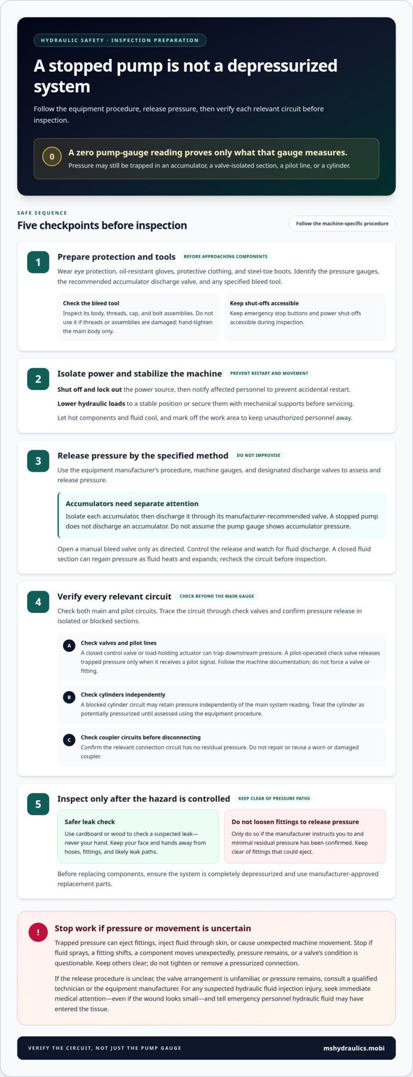
Switching off the pump does not mean a hydraulic system is depressurized. To safely de-pressurize a hydraulic system for inspection, isolate and lock out the power source, secure any raised load, and release pressure according to the equipment manufacturer’s procedure. Then verify the relevant circuits: pressure may remain trapped in valves, accumulators, pilot lines, or cylinders even when the pump gauge reads zero.
It’s reasonable to expect pressure to fall when a machine stops, but trapped fluid can leave components energized and unsafe to open. Pay particular attention to cylinders, since a blocked circuit can retain pressure independently of the main system reading.
This guide outlines a practical sequence for preparing the machine, releasing and checking pressure, and recognizing residual pressure before inspection. It also explains why valves, accumulators, and cylinders need separate attention, and when a suspected leak or uncertain pressure state means work should stop until the hazard is controlled.
Key Takeaways
- Use the accumulator’s manufacturer-recommended discharge method after isolating it, and handle manual bleed valves carefully.
- Keep clear of fittings that may eject under pressure, and never use your hand to locate a hydraulic leak.
- Check for pressure retained downstream of closed or pilot-operated check valves, including in pilot lines.
- Treat a cylinder as potentially pressurized even when the pump gauge reads zero; use the equipment’s procedure to relieve and assess trapped pressure.
How Should Hydraulic Systems Be Safely Depressurized?
Wear eye protection, oil-resistant gloves, protective clothing, and steel-toe boots. Follow the equipment manufacturer’s procedure, using the machine’s pressure gauges and designated discharge valves to assess and release pressure.
-
Gather Recommended PPE and Tools
Put on the listed protective equipment before approaching hydraulic components. Before starting, identify the system’s pressure gauges, the manufacturer-recommended accumulator discharge valve, and any specified bleed tool.
Inspect the bleed tool’s main body, threads, and cap or bolt assemblies. Don’t use it if threads or assemblies are damaged, and hand-tighten its main body only. A zero reading at the pump gauge doesn’t prove a cylinder or isolated circuit is depressurized.
-
Follow Safety Precautions
Shut off and lock out the power source, then notify affected personnel to prevent accidental restart. Lower hydraulic loads to a stable position or secure them with mechanical supports before servicing. Let hot components and fluid cool, and mark off the work area to keep unauthorized personnel away.
Check both main and pilot circuits, following the manufacturer’s pressure-release procedure. Don’t loosen fittings to release pressure unless the manufacturer instructs you to and minimal residual pressure has been confirmed. Before replacing components, ensure the system is completely depressurized and use manufacturer-approved replacement parts.
Before disconnecting a mobile-equipment quick coupler, confirm its circuit has no residual pressure. Don’t repair or reuse a worn or damaged coupler. Keep emergency stop buttons and power shut-offs accessible during inspection.
-
Use Accumulator and Manual Bleed-Valve Precautions
Isolate each accumulator, then discharge it through its manufacturer-recommended valve. A stopped pump does not discharge an accumulator, which can retain pressure while the main system is off. Follow the equipment-specific procedure, and don’t assume the pump gauge shows accumulator pressure.
Open a manual bleed valve only as the manufacturer directs, controlling the release and watching for fluid discharge. A closed fluid section can regain pressure as fluid heats and expands, even after shutdown. Recheck the relevant circuit before inspection, and stop if pressure remains or the valve’s condition is questionable.
Risks of projectile fittings and hydraulic fluid injection
Trapped pressure can eject fittings, inject hydraulic fluid through skin, or cause unexpected machine movement. These hazards remain during inspection, even after the pump stops.
-
Prevent Hydraulic Injection Injuries
Check suspected leaks with cardboard or wood, never your hand. A pinhole stream may be hard to see, but hydraulic fluid can penetrate skin. Keep your body clear of hoses, fittings, and likely leak paths while checking for spray.
Before inspection, use the equipment’s depressurization procedure and keep people clear of components that could move or discharge fluid. If a hose or fitting is damaged, stop work and arrange mobile hydraulic repair rather than continuing around a suspected high-pressure leak.
-
Recognize Injection and Projectile Risks
Look for leaking fittings, damaged couplers, and hoses that may still contain pressure. Pressure can force a fitting from its connection like a projectile, injuring anyone nearby. Retained pressure acting on a cylinder or other actuator can also cause unexpected movement.
Keep your face and hands away from connection points, and don’t test a leak by touch. Treat any suspected pressurized leak as a hazard, not a minor seep. If hydraulic fluid contacts skin or eyes, follow the applicable emergency first-aid procedures promptly.
- Seek immediate medical attention for any suspected hydraulic fluid injection injury, even if the entry wound looks small. Tell emergency personnel that hydraulic fluid may have entered the tissue. Follow emergency first-aid procedures if fluid contacts skin or eyes, and don’t delay medical care while assessing the injury yourself.
- Stop the inspection if a fitting shifts, fluid sprays, or a machine component moves unexpectedly. Keep others clear of the hazard area, and don’t try to tighten or remove a pressurized connection. Resume work only after the pressure hazard and movement risk are controlled according to the equipment’s procedure.
Pressure retained by check valves and accumulators
A stopped pump doesn’t establish that every circuit is depressurized. Consult a qualified technician or the equipment manufacturer if the release procedure is unclear, pressure remains, or the circuit’s valve arrangement is unfamiliar.
- Trace the circuit through each check valve before inspection. A closed control valve or load-holding actuator can trap pressure downstream, while a pilot-operated check valve releases trapped pressure only when it receives a pilot signal. Find the required pilot-control procedure in the machine documentation; don’t force a valve or fitting to release pressure.
- Consider accumulators separately from the pump circuit. An accumulator can retain pressure while the main pump is off, so isolate it and use its manufacturer-recommended discharge method. Record the accumulator and discharge steps in the maintenance checklist, then confirm its condition before servicing connected components.
- Check both main and pilot circuit pressure before beginning work. A zero pump-gauge reading doesn’t show that a blocked downstream section has released pressure. Include circuit locations, isolation points, and release checks in the machine’s written procedure so trained, authorized personnel can follow the same sequence.
- Assess couplers only after releasing pressure in the relevant connection circuit. Couplers that connect smoothly with minimal effort indicate that pressure has been released sufficiently for that connection task. If a coupler resists engagement or separation, stop rather than forcing it; consult the equipment procedure or a qualified technician before continuing.
- Keep training and documentation specific to the machine’s valve layout. A checklist should identify check valves, pilot lines, accumulators, pressure-check points, and the required release method. Update it after a component replacement or circuit change so the procedure reflects the equipment’s current configuration.
Trapped pressure in hydraulic cylinders
Lower each hydraulic load to a stable position or secure it with mechanical supports before releasing pressure. A cylinder can retain pressure after shutdown, so a zero pump-gauge reading alone doesn’t establish a safe condition.
-
Account for Trapped Cylinder Pressure
After shutting off hydraulic power, move levers, joysticks, and buttons through their full range several times in every direction, following the machine’s procedure. This may route trapped pressure back to the tank, but don’t assume every cylinder has released pressure.
Check cylinder position and movement from a safe location. A plunger that remains extended or appears stuck is a warning that pressure may remain. Don’t disconnect a hose or fitting to test it. Pressure released from a cylinder can cause serious injury or unexpected movement.
-
Lower or Support Hydraulic Loads
Place attachments and raised loads in a stable position before releasing pressure. If lowering isn’t possible, secure the load with mechanical supports, blocks, or safety stands suited to the equipment. Never rely on a hydraulic cylinder alone to hold a suspended load during inspection.
Keep personnel clear of the load’s movement path while positioning supports. Confirm each support is stable before continuing with the machine’s pressure-release procedure. Don’t disconnect hydraulic lines while a load is unsupported, since trapped pressure can allow the cylinder or attachment to shift.
- Reassess the cylinder before inspection. Compare its position with the machine’s expected safe state, and treat an extended plunger or unexpected movement as a stop condition. Keep protective equipment on, and don’t loosen fittings to release residual pressure. If a cylinder remains pressurized or fails to move correctly, arrange hydraulic cylinder rebuild support.
Ms. Hydraulics LLC
Ms. Hydraulics LLC can help when a machine’s pressure state remains uncertain, a cylinder does not move as expected, or inspection reveals damaged hydraulic components. Its technicians provide on-site diagnostic services and mobile hydraulic repair for equipment that needs assessment or repair at the work location.
For follow-up work, Ms. Hydraulics LLC also provides heavy equipment maintenance, hydraulic hose fabrication, and hydraulic cylinder rebuilds. This support is relevant when a pressure-release concern points to a leaking hose, a cylinder that needs rebuilding, or a broader equipment issue. Clear information about the machine, affected circuit, and observed symptoms helps define the work required.
If a cylinder or circuit still presents a pressure hazard, stop work and contact Ms. Hydraulics LLC to discuss the equipment’s inspection or repair needs.
Build a Safer Standard for the Next Inspection
Knowing how to safely de-pressurize a hydraulic system for inspection is a starting point for consistent maintenance. Use the same disciplined approach whenever equipment is opened, repaired, or returned to service. For operators managing hydraulic utility vehicles and work trucks, coordinating hydraulic safety checks with comprehensive vehicle upkeep from specialists like Eagle Transmission & Auto Repair helps maintain overall mechanical reliability. Clear records of the work performed can help technicians identify recurring component issues and make informed decisions about future maintenance.
When inspection reveals damaged hoses, cylinder wear, or broader equipment needs, Ms. Hydraulics LLC provides Hydraulic Hose Fabrication, Hydraulic Cylinder Rebuilds, and Heavy Equipment Maintenance. These services support follow-up work based on the condition of the hydraulic equipment.
For help with a hydraulic inspection or the repair work it identifies, contact Ms. Hydraulics LLC. A careful next step keeps the focus on the machine’s condition and the work needed to address it.
Frequently Asked Questions
What are the standard steps to safely depressurize a hydraulic system before inspection?
A procedure for how to safely de-pressurize a hydraulic system for inspection starts by identifying energy sources, isolating and locking out power, and securing the load. Release pressure using the manufacturer’s method, then check the main and pilot circuits and isolated components. Confirm relevant gauges read zero, but assess cylinders and blocked sections separately. Stop if the release path is unclear.
How do you identify all hydraulic pressure sources and stored energy in a system?
Trace the hydraulic schematic from the pump through directional and check valves to actuators, noting branches that can be isolated. Include pilot lines, accumulators, quick couplers, closed valve sections, and cylinders in the energy map. Also account for fluid trapped in a closed section that may heat after shutdown. Mark each test point and component on a written circuit checklist before opening any connection.
How can you verify zero hydraulic pressure at every circuit and test point?
To determine how to safely de-pressurize a hydraulic system for inspection, follow the manufacturer’s procedure and use the designated gauge or test point for each isolated circuit. Record main and pilot circuit readings, then use the prescribed control sequence to assess actuator pressure. A gauge reading alone cannot prove a blocked cylinder is empty. If pressure remains, keep the circuit closed and escalate the inspection.
What lockout/tagout procedures apply to hydraulic system inspection in the United States?
At worksites in Cleburne and the Dallas-Fort Worth area, start with the employer’s written lockout/tagout process: notify affected personnel, shut down equipment, isolate and lock the power source, and prevent restart. Account for hydraulic stored energy separately from electrical isolation, including elevated loads and pressure-bearing components. Follow machine-specific instructions to release and verify pressure; a tag or stopped engine doesn’t prove the hydraulic system is depressurized.
How do you safely depressurize hydraulic accumulators before maintenance?
Isolate the accumulator from the working circuit, then discharge it through the manufacturer-recommended discharge valve. Keep the machine’s procedure available because the accumulator type and valve arrangement determine the correct sequence. Confirm stored pressure using the designated method before maintenance; a pump gauge can read zero while the accumulator remains charged. Don’t loosen an accumulator fitting instead of using its discharge valve.
How should hydraulic pressure be relieved when a system has no dedicated bleed valve?
Use the manufacturer’s designated pressure-release method, such as operating specified controls or using an approved discharge point. Don’t loosen a fitting just because no bleed valve is visible. If the equipment procedure directs using a pipe joint as a last resort, trained personnel should follow that instruction only after confirming minimal residual pressure, with a thick rag over the joint and a container ready to catch leaking oil.